


imkidd57
-
Posts
43 -
Joined
-
Last visited
-
Days Won
6
Content Type
Profiles
Forums
Downloads
Posts posted by imkidd57
-
-
asivery (the current developer of WMPpro and ElectronWMD) has produced replacement screens; the first batch went on sale early this morning UK time and cost less (65 EUR + 20 EUR shipping) than those from MD Gadgetry:
https://lectronz.com/products/rh10-oled-module
At the time of writing, there are 2 left from the initial batch ...
-
Having a standard MD in the unit is enough to put it in MD mode and is sufficient for a connection to electron WMD.
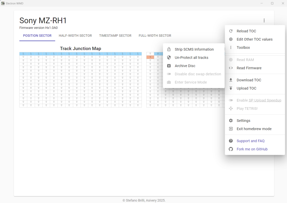
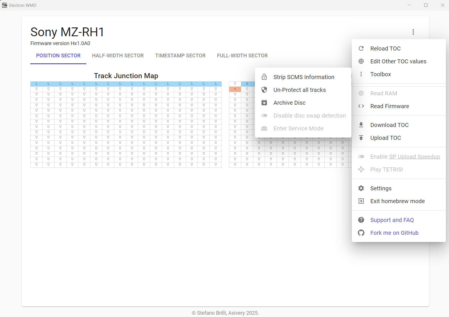
@Syrius Which of the options are you wanting to use? AFAIK the SP speed upload feature has not been implemented yet for the RH1.
However for the 'Strip SCMS' and 'Unprotect all tracks' options, these are found after you have enabled the homebrew shortcuts slider in 'Settings' then 'Enter homebrew mode' -> 'Toolbox':
-
How was the speaker cable? On most I have seen (and bought) it is completely rotten and the issue is that the PSU is in one of the speakers.
-
On 10/30/2024 at 10:41 PM, sfbp said:
Doesn't the PCLK-MN10 (and MN20) do this by default?
That's all very well, but where can one get the original PCLK units these days, for a decent price? The Cubilux is available on Amazon for about 20 quid and is thus a potential realistic solution for those that don't need the legacy editing but want simple but accurate track marking. In my experience it has been difficult for people to find a device that will stimulate track marks when there is no silence on a CD.
-
Excellent - thanks very much for adding to the knowledge about this unit!
-
Hi and welcome to the SI forum!
The basic 'No Disc' problem may be the sensor in the MD unit that tells it when a disc has been inserted after the lid is closed. It is a small black pin on the left-hand side of the MD base when the lid is open:

This pin engages with one of the holes on the underside of the minidisc itself, and the pin gets pushed down when the minidisc is inserted and the lid closed:

In older machines, this pin can become less sensitive and requires to be pushed down further.
The malfunction can be associated with particular discs though. Do you have another to try? Otherwise you can test by putting a piece of sellotape over the pin to stick it down, then put the minidisc in and try closing the lid. If it reads the disc then you can assume it is the hole depth not being enough.
I have overcome this problem by putting a tiny piece of paper into the hole of the minidisc itself, and pressing it down hard to flatten it within the hole using a small screwdriver. The effect is to raise the base of the hole and make it push that pin down a bit further when the lid is closed.
Sadly, on some units the pin gets snapped off due to rough treatment and requires replacing.
BTW, the 'white gunk' you saw on the spiral is lithium grease which is supposed to be there to lubricate the worm drive mechanism. If you cleaned off the excess then that's probably fine as there should be enough remaining in the thread to work.
-
 1
1
-
-
Great! Good luck with the repair 😊...
-
Hi - I have an STL file for the lever lock assembly for a 333es, and comparing the service manuals it has the same part number... so very probably the same thing.
Have attached it here, and will add the link to the source page if I can find it again!
<edit: source page is here on SI Forums:>
Anyway, I can print a couple for you in black or transparent PETG; unfortunately don't have any white PETG filament. Where are you located geographically?
For reassembly and alignment of the disc tray mechanism, I recommend watching this video on YouTube as it covers a number of problems with the 333es such as belt change, disc tray adjustment, and recording issues. Again,comparing the service manuals, the principles are probably the same for the 555es.
TL;DR... at exactly the 6min timepoint, he discusses and shows the alignment of marks on the rack, gear, and slider (which is also in the 555es manual p16).
-
 1
1
-
-
When you say 'streaming', does this mean downloading files from the NH3D to the PC? The word 'streaming' is usually used in the context of real-time playback, whereas the downloading is often several times faster than that.
Although from WMDPro 1.4.0, where the support for HiMD units and downloading HiMD files in included, the use of all HiMD units with WebMD Pro is in its infancy. Some will only work when set to standard 'MD' mode for uploading and downloading the older format files SP, LP2, LP4 (eg for me the RH1 and NHF800 work) but for others such as the NH1, in my setup it doesn't even seem to be recognised. As the NH3D is approximately from the same time period as the NH1, you may find the same situation that it's not recognised.
-
There are some very fine linear springs in the OPU assembly on which the lens 'hangs'. Focusing on the disc track is achieved by a small electrical coil linked to the lens, which moves the lens up and down until it obtains an authentic location address on the disc. It may be that something is impeding the coil from moving the lens upwards against the push of the springs, whereas with the unit upside down it gets assistance from gravity, as @sfbp says, to move further towards the disc surface. The CD discs could be read OK because the range of the lens is still within the tolerance, given the higher reflectivity and that the information is in the form of true pits and lands, rather than relying on the MO disc substrate polarisation effects to read an MO disc.
Some possibilities:
- Lens is not completely clean
- Something mechanical obstructing the lens movement and preventing the upwards travel
- Weak circuit voltage which means the coils can't pull the lens up enough, against the force of the spring
- A combination of undervoltage and weak laser
The first is easy to test: try cleaning the lens again, but this time with some distilled water. I have found that some isopropyl alcohol leaves a slight haze on the lens.
The second.. have a close look at the OPU under magnification and check for hairs or dust that might be interfering with the lens travel
The third and fourth: this will probably require the adjustment procedure of the unit, but for the MZ-R50 is requires a bit of soldering to get it into test mode; it can't be done from the remote as for newer models. Before doing this though, one thing may be worth trying. With a full battery, open and close the lid of the MZ-R50 without an MD in it, and leave closed for around 30 sec; then repeat this 15-20 times. This action forces the OPU mechanism to move the lens up and down to its fullest extent either side, to check if a disc has been inserted, and it may be that a bit of 'exercise' might be of benefit. If your unit is in near mint condition, then it may not have been used very much for a long time and so using it more could free things up.
-
6 hours ago, fourbanks said:
The battery is now available as well, it seems
AIWA LIB-902 MD Player AM-F70/F80 AM-C80 AM-F5 / Sharp ST60 Battery - 3.7 700mAh | eBay
40 quid - ouch! Also, seems it 'must be charged with a Micro-USB cable', so it may not do so inside the MD unit.
The Trustfire/LIB-902 3DP shell combination does charge inside a JVC XM-R70.
-
Yes I got one of those from the same seller and it works fine.
For those that have a 3D printer available, there is a version available on Thingiverse:
-
This page on Reddit has a post about half-way down from a user that says the RM-CRX20 works with their MD units MZ-RH10 and MZ-N707:
...and this page in the Minidisc Wiki says the standard remote for e.g. the MZ-707 is the RM-MZ4R (has no LCD screen) but either RM-MC10L and RM-MC11EL (both have LCD screens):
https://www.minidisc.wiki/equipment/sony/portable/mz-n707
However that is not the same thing as saying those remotes will work properly with the MPD-AP20U! There may be extra circuitry or firmware in the RM-CRX specific remote that accsses function of the MPD unit, but looking at its user manual, the description and pictures of the remote don't reveal anything special and that it has a screen.
Unless you know anyone who has the MZ-N707 and can lend you it to try, I guess it might come down to taking a risk and buying one of those remotes on eBay or something.
-
Indeed... so we can expect some HiMD units then? 😉
-
Hi and welcome to the MD universe!
Looking at your first video, I was struck by the amount of surface material present on the disc's upper surface. Normally they should be glossy and without scratches or deposited material. If there is crud stuck on there, then it could explain why the record head cannot contact the surface consistently, and stops.
Do you have another, possibly cleaner disc to try?
Since the machine is new to you, another possibility is that it's the record head itself which is producing deposits, so would be worth cleaning the underside of the record head with some 70% isopropanol to see if that helps. Even if it isn't the source of the deposits, it may have picked some up during the write attempts.
-
1
-
-
OK well finally back with a report of success with the Drive B encoder. Did the connection reversal for pins A and B of the encoder (1 and 3 on the PCB diagram from the service manual). No need to cut the tracks as both solder ring pads had been lost but I still had to undo the track repair. Also, in the process of de-soldering the encoder for the nth time, the solder pad for pin 4 also came off, so had to make a new bridge connection for that.
Another figure of the rather messy repair: hairs on the area were from cotton buds during cleanup. Pink stuff is nail varnish remaining from the earlier track repair.

Anyway after covering the area with Kapton tape and reassembling the rewired PCB back into the front panel, all functions of the encoder were exactly as anticipated (clockwise + counter clockwise) and the push-button switch works fine. Earlier worries about the amount of force needed to push the switch were allayed and it is not so forceful as to move the whole deck.
With the above success I revisited the left-sided encoder (Drive A) of the W1 and rewired it according to the principle above, which is a much more solid repair as all the legs can be soldered to the board and the bridge wires added. It's a different wiring layout, which I can include in a repair section of the MD Wiki as requested.
Thanks everyone, especially of course @kgallen for all the advice.
-
1
-
-
Many thanks again @kgallen. Sorry for late reply - Farnell stock control in a bit of a pickle but I've fianlly got more encoders now. Will report ASAP.
-
@asivery - very nice work indeed with the .aea files. I was able to upload some previously extracted files to an MZ-N10, and it was very quick (about 25s for a 3.14 min track). In fact it was so quick that could I ask if there is any conversion stage prior to the upload i.e. is this true SP being uploaded, as opposed to an LP2 labelled as SP (what we used to call 'fake' SP).
-
Well repairing drive B side turned into a flipping nightmare! The solder ring pads surrounding the holes for A and B of the encoder became detached - probably too much messing about with the soldering iron, sucker, flux, desoldering ribbon, and IPA. Then the A and B legs fell off the second encoder after trying to carefully bend them out of the way to reverse the connections. Track repair with fine wire was successful but was then very hard to connect the wires to the stumps of A and B; and now the encoder itself may be knackered 🤣. To highlight the nightmare, I ordered some more encoders from Farnell but all I received today was a bag of hexagonal nuts 🤪. I do wonder at their warehouse QC...
On review this whole affair may be better solved by reversing the A & B connections at the end of the circuit board where the tracks from the pins lead to a ribbon connector that joins with the central display board, rather than messing about with the fragile pins of the encoder. The PCB appears to be one-sided; so now that the ring pads for A and B have gone, and the tracks have become non-continuous, after looking at the diagrams in the service manual I am proposing to take jumper wires from each A & B leg and solder to the reverse points on the pads of the distant ribbon connector (pins 8 & 9). It's not very far (~2 cm) and should be far easier to manipulate than bending the encoder legs again.
Any thoughts?
Here is the schematic from the SM:

... and PCB mask with actual positions:

-
21 minutes ago, kgallen said:
Thanks for the update and info. That is weird. I wonder if Sony had a custom part made for some reason. I’ve suspected that before - the headphone volume control on one of my MDS-E10 or E12 didn’t seem to be a standard part. That mounts to the PCB to the side so the flat on the shaft needs to be at a different position to get the knob marker to line up between the min and max position. Also I couldn’t find the correct resistance (I can’t remember now if it was 1k or 5k).
Not at all - thanks so much for all your help 😀! I'll add some more pictures during drive B modification, and hopefully will be a useful resource in case a fully compatible encoder can't be found.
I noticed that the same Sony part number for the encoder is listed for the MDS-JE520 and JB930.
-
As a practical update, with your advice kgallen I reversed the connections A and B of PEC11L onto the PCB with some thin insulated wire, and the encoder rotation is now as it should be: turning clockwise increases the track number count, and also progession through the menus. Push switch still works as expected and the whole left-hand side PCB fits back onto the main front panel.
Because of the lack of support by the two pins now not soldered onto the board, as a precaution, I added a collar to the threaded bit of the shaft so it would fit exactly in the hole of the main front panel (you can see that the Sony original part is a lot thicker (9mm) and a snug fit in the hole). This should help counteract any inadvertent sideways stress on the remaining PCB connections during rotation of the AMS knob.
-
Thanks very much for all the info, kgallen!
Second time around I chose the PEC11L as it was a low-profile version, and couldn't see a PEC12 equivalent and I never thought there would be a difference in rotation. All the PEC12Rs had a base which was too thick (~6mm); even the PEC11R I got first time. It's true though that both PEC11s are threaded. Here the three encoders to show the difference:

-
Yes it's weird! I've looked through the PEC11L datasheet but to my untrained eyes I can't see anything about variants with different rotation directions. I have attached it in case there is something I missed.
It may come down to something I've done in the soldering; e.g. accidentally bridged to another pin or something! I will go back and check under magnification.
-
Thanks - well there has been some good progress. The low profile encoder fits great and allows the PCB to be replaced properly in the front panel, without any stress on it or the other switches. Also, the plastic AMS knob fits better on the shaft and no filing is needed to get it on (or off).
Reconnected the ribbons and wires, powered on the deck and it works! Rotating the dial moves through tracks on MDs, and the push-on switch plays the track. In the menu the rotation similarly moves back and forth through the options, and the push-on selects the one arrowed. However, going forward through the numbered tracks on an MD, or going through the menu options is via an anticlockwise rotation, whereas it should be clockwise (checked on a working MDS-W1 deck).
I don't know enough electronics to understand if this can be corrected, say by swapping the pins of the A and B contacts where they are soldered to the board (see 'quadrature output table' in previous post, lower left hand diagram, where I presume CW and CCW are the rotation actions). Would anyone be able to suggest a way of reversing the current action?
-
1
-


MZ-NE410 NV Reset :(
in Technical, Tips, and Tricks
Posted
OK I couldn't understand some of the instructions on the link you gave; not surprising things errored out. Perhaps more importantly, yours isn't an MZ-R xx unit so the instructions are likely to be not the right ones.
I suggest going to the Minidisc Wiki and download the service manual for your actual unit:
https://www.minidisc.wiki/equipment/sony/portable/mz-ne410
On page 24 is the 'Overall adjustment' instructions and you can try to follow those. Normally I'd say do the preceding temperature and voltage checks but give the overall adjustment a go first - it might work.